Introduction to conductivity and mechanical functionality of grounding connections
Electrical components on trains must be protected against short circuits to prevent damage to the components and injury to passengers or staff.

Introduction
Trains have many electrical components located on the upper part or under the passenger cars, which need to be protected against short-circuit incidents. If such events result in power supply disruption, it can cause severe damage to the components or even injury to passengers and maintenance personnel.
Electrical safety standards in trains
There are many standards related to electrical safety in trains, which help to prevent these cases, some of which are listed below for illustration.
|
Standard for railway transport |
Topics |
| DIN EN 50343 (EN 50343) | Rules for cable installation |
| DIN EN 61439-1 (IEC 61439-1) | Low-voltage switchgear and control gear assemblies |
| DIN EN 61373 (IEC 61373) | Shock and vibration tests |
| DIN EN 60721-3-5 (IEC 60721-3-5) | Part 3: Classification of environmental condition groups and their severity levels |
| DIN EN 60068 (IEC 68-* or IEC 60068-*) | Environmental testing including tensile, bending, salt mist, electrical resistance, sand and dust, vibrations (see also IEC 61373), temperature changes, dry heat, sealing, shocks (see also IEC 61373), torsion, torque. |
To prevent short-circuit incidents, the current from the power source must be diverted directly to the ground through electrical bridging paths, which require a connection for attaching cables. The connection is crucial for ensuring the optimal level of conductivity under all possible conditions. As with any safety-critical connection, the installation process must ensure the integrity of the connection at every installation, and the connection must operate long-term.
Historically, tests have shown that proper levels of conductivity can indeed be achieved using grounding spike solutions (which are commonly used in these applications), but the mechanical functionality of the joint may sometimes be insufficient. This is usually due to poor installation, resulting in insufficient contact with the material to achieve the required conductivity. This poses a risk that the electrical bridging will not be fully functional during operation. The differences in performance and functionality of such a joint "on paper" and in reality can be significant.
The desired state of the grounding joint system should therefore ensure the following:
- The required level of conductivity corresponding to the risk of a short-circuit case.
- Mechanical properties necessary to ensure long-term functionality 1).
The three fundamental tangible system elements of the grounding joint are:
- Sheet material (type of material, material thickness, contact area)
- Grounding cable configuration
- Connecting component (diameter, material, etc.)
Each of them plays a role in achieving the above goals 1) and 2).
There are several other intangible factors that play a role in each successful joint, which we will discuss in more detail in part 2 of this article. The first is reliable control and feedback of suitable installation parameters. The second is proof/documentation of each "successfully executed" grounding joint.
Howmet Fastening Systems (HFS), based in Kelkheim, Germany, conducted extensive testing with the support of the International Product Safety Institute in Bonn to understand the relationship between mechanical functionality and electrical conductivity of joints based on the above-defined criteria. This study summarizes the test results.
Results
ConductivityTesting was performed using the Cam-Safe installation system, which ensures proper installation of the connecting component: results therefore do not take into account variability of the joint caused by non-uniform installation processes.The graph (image*) shows the relationship between material, time, material thickness, and current for size M6. For alternating current, the function is labeled as RMS (Root Mean Square) on the y-axis. Short-circuit resistance The shorter the duration and the higher the current, the greater the peak I and the induced electrodynamics force become relevant. Conversely, the longer the current flows, the more the level of heat increases, reaching critical values, which is the basic effect for the ability to withstand short-circuit (> 1 s). |
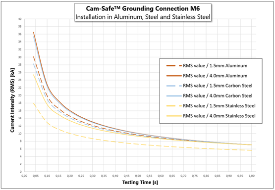 |
Below are the key findings from the testing summarized
- Thicker material has better properties in all cases than thinner material.
- After 1 second, almost all materials were at the same level due to the development of heat and resistance to the electrodynamics force. The exception was 1.5mm stainless steel, which has lower parameters due to its natural properties.
- Shorter time periods are most critical for short-circuit cases. The time period of 0.05 seconds to 0.10 seconds is most relevant, even in the context of railway applications.
- It is in the shorter time intervals that the differences between types and thicknesses of materials are most noticeable.
- Aluminum allows the highest current, which decreases the longer the test lasts.
- Corrosion-resistant steel is fundamentally lower, but the difference decreases with longer duration. This effect is caused by electrodynamics forces, which are better supported by the strength of the steel material.
- Thicker material ensures greater conductivity. If conductivity is a priority, then the best performance is offered by aluminum sheet. However, carbon steel has only slightly lower conductivity, while providing much better mechanical properties for both 1.5mm and 4mm materials.
Contact area
Our testing showed that the decisive contact is created in the hole itself (whether drilled, punched, or cut out), not on the upper or lower side of the fastened components.
This means that the sheet material can be provided with a outer insulation layer, for example, plating, protective films, or paint, without having a negative impact on conductivity; only the material inside the hole must remain in a raw state. It is important that the inner surface is clean, as oil and dirt can create a barrier and limit contact. When using aluminum, the hole must not be anodized; if necessary, the hole is re-drilled after anodizing to restore the raw material state in the hole.
On the other hand, mechanical functionality depends on the contact of the connecting component with the top and bottom of the material.
Material thickness
Tests showed that material thickness (in combination with hole size / diameter of the connecting component) plays an important role in grounding connections, especially for alternating current applications. Installation into a structure with greater thickness can transfer greater mechanical forces and dissipate more current and heat than thinner structures in the same time period.
Thinner material limits the conductivity and mechanical functionality of the joint, but usually offers a lighter weight solution. Using thinner material allows for less margin of error in case of poor installation, where any loss of contact area has a greater relative impact on the level of conductivity. See our recommendations for joints made from thin sheets.
Smaller contact area = large electrical resistance = lower conductivity
Larger contact area = smaller electrical resistance = higher conductivity
Type of material
For grounding joint constructions, three materials are typically used: aluminum, carbon steel, and stainless steel. Aluminum is an excellent conductor of current and heat. Stainless steel conducts current and heat less effectively, but provides much better mechanical strength. Carbon steel lies somewhere in between; it has good mechanical properties and its thermal and electrical conductivity is much better than that of stainless steel.
The table below shows the relevant specifications for aluminum, stainless steel, and carbon steel. Copper is listed as a reference material, given its significance in electrical applications.
| Sheet material | Tensile strength | Yield strength | IACS Conductivity | Electrical conductivity |
| unit | [N/mm2] | [N/mm2] | [%] | [S.m/mm2] |
| Copper | 250 min | 180 min | 100 | 58.5 |
| Aluminum | 180 min | 80 min | 62 | 35.9 |
| Carbon steel | 290 min | 140 min | 18 | 10.5 |
| Stainless steel | 500 min | 200 min | 2 | 1.4 |
The material should be chosen based on a combination of the required level of conductivity and mechanical functionality of the joint.
Cable specifications
The cable cross-section must be specified by the customer to meet the specific requirements of the application, including the choice of material, material thickness, and connecting component. If the ability to withstand a short circuit is too low, the resulting heat will be too high, which can lead to cable burnout.
Each connection point must withstand the highest requirements defined in the relevant regulations to ensure safety throughout the application's lifetime. It is important that the chosen connecting component provides the mechanical functionality needed to secure the cable.
Mechanical Functionality
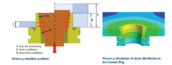
When selecting a connecting component for grounding applications, it is important to choose one that maximizes surface contact in the hole. The diagram below shows a cross-section of a correctly installed grounding rod.
Incorrect Installation
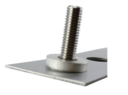
Sloping installation (with a gap between the contact ring and the plate, as shown in the above image) can be the result of incorrect installation angle and/or prolonged installation time. In addition to negatively affecting the predictability of surface contact in the joint, it can also lead to insufficient mechanical functionality (poor torque) and the risk of complete failure. With appropriate tooling concepts, such as the Cam-Safe system, this failure mode can be significantly limited.
|
|
One of the biggest concerns is contact variability due to inconsistent installations. Poor installation, where the desired surface contact is not achieved, directly impacts the conductivity level of the joint. Ideally, a system that guarantees a method for achieving 100% desired contact or at least identifies incorrect installation that can be replaced would be ideal. Image of unsuccessful (sloping) installation |
After proper installation, it is important to ensure long-term durability. A connecting component that allows for a permanent connection is recommended. Connecting components, such as Cam-Safe grounding spikes (which consist of two parts: a tensioning spike or nut and a contact ring), use a force-controlled installation process to expand the connecting component in the panel hole, creating a permanent connection with 1) maximum surface contact, 2) resistance to vibrations and manipulation, and 3) minimum electrical contact resistance.
Conclusion
In working with grounding connections in railway applications, safety must always be an absolute priority. The results indicate several important aspects in designing the connection structure: the specification of each of the primary components of the connection is important in achieving a balance between conductivity and mechanical functionality of the connection. It is clear that conductivity and mechanical functionality go hand in hand. Without proper installation and proper contact surface area between the fastening element and the base material, the conductivity of the connection is at risk.
Part 2 will address the benefits of the Cam-Safe system in achieving successful installations with guaranteed properties and mechanical functionality.
Interested in Cam-Safe products?
Do not hesitate to contact our connectivity business department, where we will be happy to assist you in selecting the right products for your needs.
Contact us