Aluminum Platform – Assembly Manual
This manual provides complete instructions for the assembly and installation of aluminum platforms for vehicle superstructures. It includes technical specifications, detailed drawings, step-by-step assembly guidelines, and information about profiles, mounting corners, and accessories. The document also covers delivery options, recommended materials, reinforcement methods, and warranty conditions. Designed for professionals and technicians, it ensures correct installation, structural safety, and long-term functionality of the aluminum platform.Contents of the Assembly Manual
- 1. Instructions for Assembling the Aluminum Platform
- 1.1. Platform Construction
- 1.2. Delivery of the Platform
- 2. Platform Assembly
- 3. Basic Profiles for Modular Aluminum Platform
- 3.1. Frame Profile
- 3.2. Cross Profile for Frame Profile
- 3.3. Auxiliary Profile
- 3.4. Profiles for Modular Aluminum Floor
- 3.5. Mounting Corners
- 3.5.1. Pre-drilled Mounting Corners for 80x35 Columns
- 3.5.2. Pre-drilled Mounting Corners for LIGHT Columns
- 3.5.3. Non-drilled Mounting Corners – 70 mm Frame
- 3.5.4. Accessories for Platform Corner Connectors
- 3.5.5. Non-drilled Mounting Corners – 90 mm Frame
- 3.5.6. Non-drilled Mounting Corners for MIDI Columns – 90 mm Frame
- 3.5.7. Non-drilled Mounting Corners – 108 mm Frame
- 3.6. Parts for Aluminum Platform
- 4. Platform Installation
- 4.1. Auxiliary Profiles
- 4.2. Cross Profiles
- 4.3. Frame Profiles and Steel Corners
- 4.4. Central Reinforcements
- 4.5. Front Wall Reinforcements
- 5. Warranty and Spare Parts
1. Instructions for Assembling the Aluminum Platform
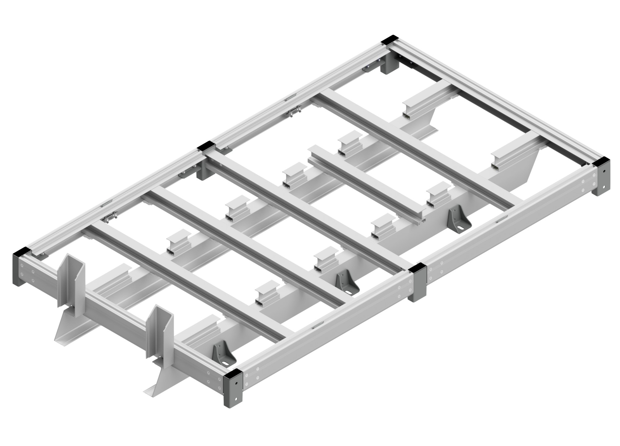
1.1. Platform Construction
Precise technical specifications and high-quality drawings are essential for the production of the aluminum platform. This process requires thorough preparation and an understanding of technical requirements. If you do not have your own design, our engineering department is ready to assist you.
For optimizing the functionality and safety of the platform, the following information is required:
- Platform drawing: If you do not have your own design, you can use our design services.
- Maximum load: Determines the platform capacity and material selection.
- Plywood thickness: Options include 15, 18, 21, 27 mm, which affect platform durability.
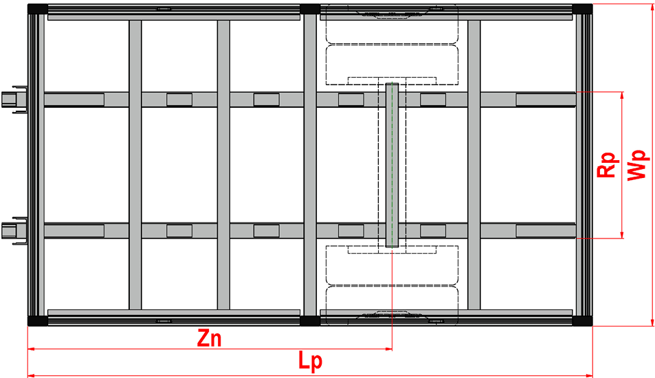
- Platform dimensions: Specify the length (Lp), width (Wp), or external body dimensions.
- Axle distance: Known as Zn, it is crucial for load distribution.
- Longitudinal beam spacing: The spacing (Rp) of the beams on the chassis is important for structural strength.
- Central posts: The number and placement of posts ensure stability.
- Lashing eyes and clamps: Their quantity and placement are essential for safe load securing.
- Types of posts: The choice of corner and central posts affects the overall construction and usability of the platform.
The aluminum platform serves as a base for various types of superstructures:
- Lightweight dropside body with AL or galvanized posts
- Lightweight dropside body with a fixed roof (no sliding)
- Dropside body with roof and side sliding system
- CS superstructures with three-sided sliding system
Based on this, the type of corner posts is selected. The type of superstructure also determines the type of front wall reinforcement, as well as corner and central connecting parts of the frame. The arrangement of cross beams depends on the axle position and plywood floor size. Assembly of the aluminum platform is carried out using PALCOM clamps and bolts.
1.2. Delivery of the Platform
The platform is delivered in several versions, depending on customer requirements: only cut profiles, cut and machined profiles without assembly, or a fully assembled platform. For the last option, higher transport requirements must be taken into account.
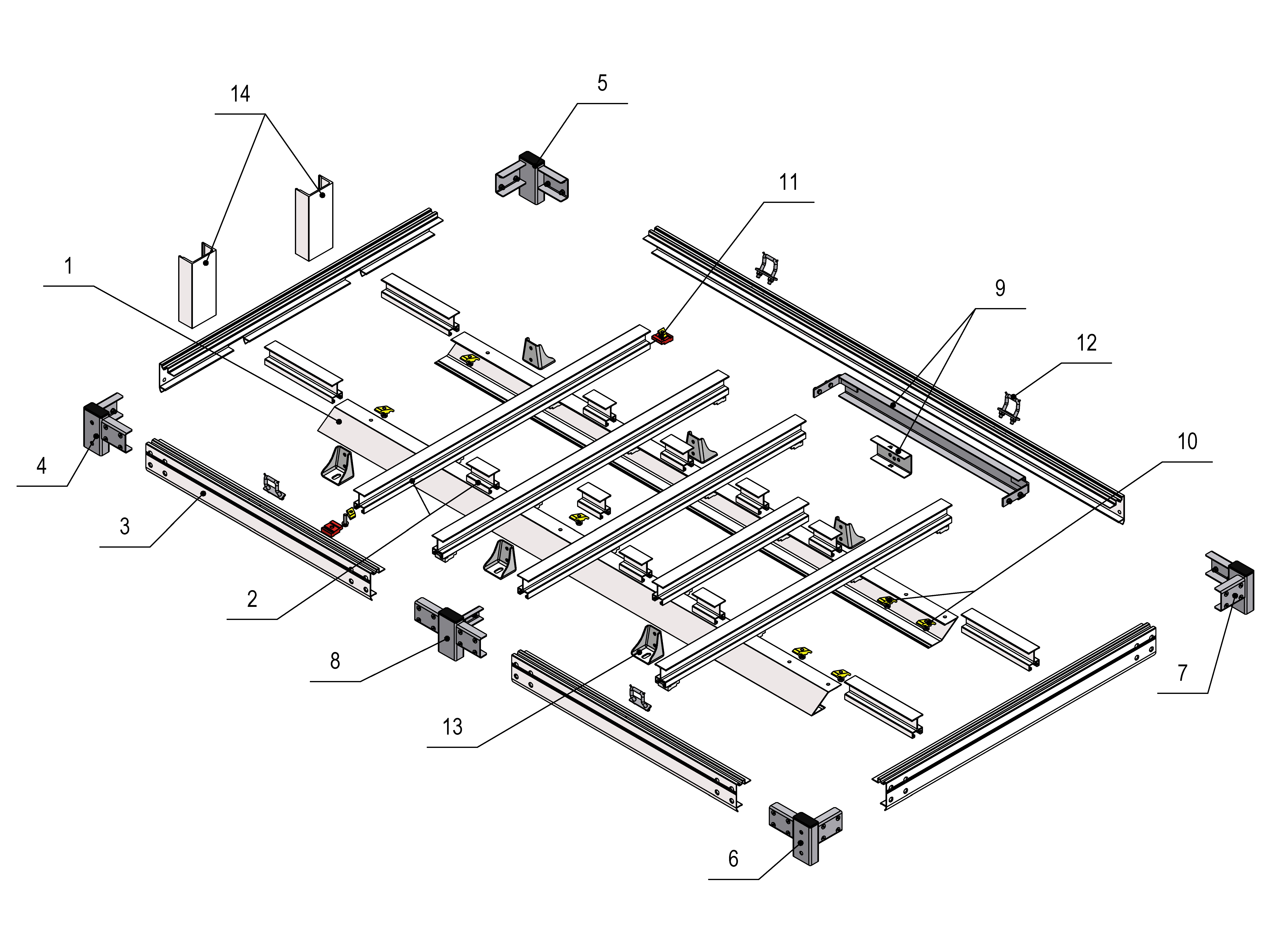
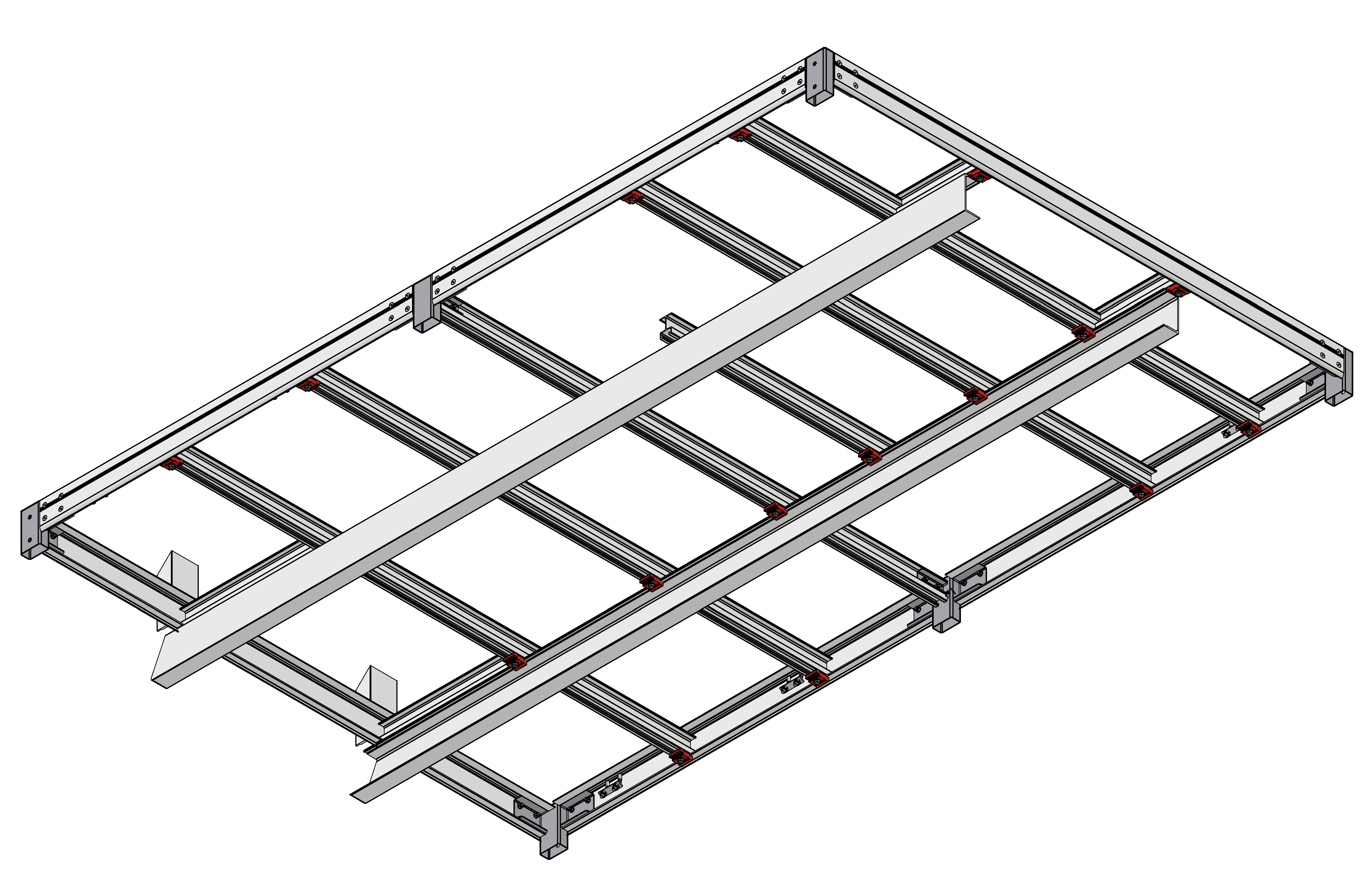
2. Platform Assembly
| Position in Assembly | Name |
| 1 | Auxiliary profile |
| 2 | Cross profile |
| 3 | Frame profile |
| 4 | Front left corner (FL) |
| 5 | Front right corner (FR) |
| 6 | Rear left corner (RL) |
| 7 | Rear right corner (RR) |
| 8 | Central corner left |
| 9 | Central reinforcement |
| 10 | Palcom upper part + M10x25 |
| 11 | Palcom clamp complete |
| 12 | Anchor bracket |
| 13 | Clamp |
| 14 | Front wall reinforcement |
3. Basic Profiles for Modular Aluminum Platform
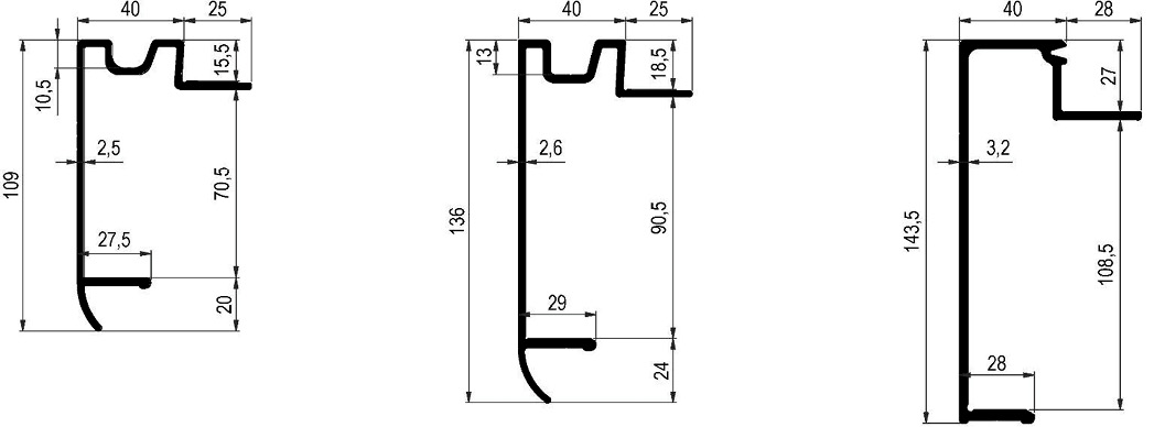
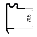
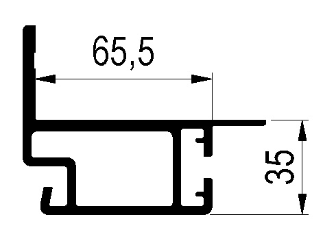
3.1. Frame Profile
| TT-number | Name | Material/Surface | Weight kg/m |
| 0431016.000 | Frame profile with groove 70 mm | Aluminum natural | 1.64 |
| 0432016.000 | Frame profile with groove 70 mm | Aluminum anodized | 1.64 |
| 0431014.000 | Frame profile with groove 90 mm | Aluminum natural | 1.97 |
| 0432014.000 | Frame profile with groove 90 mm | Aluminum anodized | 1.97 |
| 0431007.000 | Perimeter frame profile 108 mm | Aluminum natural | 2.30 |
| 0432007.000 | Perimeter frame profile 108 mm | Aluminum anodized | 2.30 |
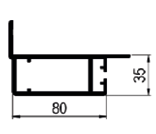
3.2. Cross Profile for Frame Profile
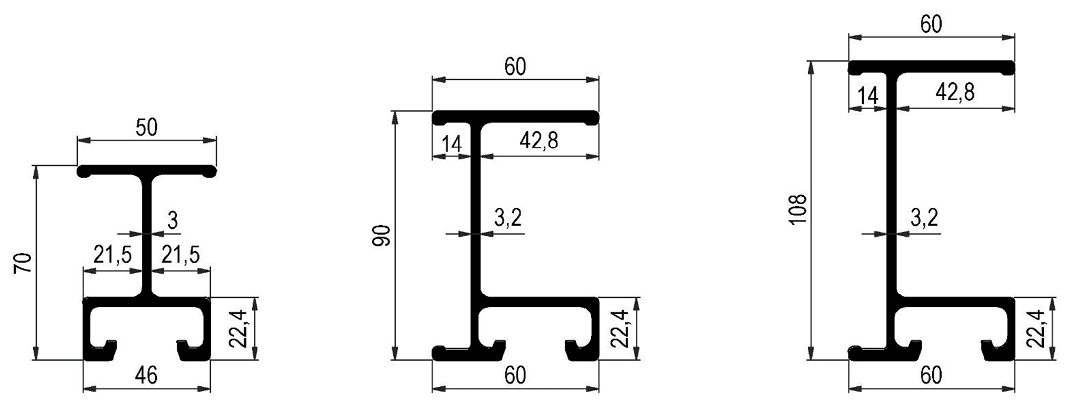
| TT-number | Name | Material/Surface | Weight kg/m |
| 0431015.000 | Cross profile 70 mm | Aluminum natural | 1.73 |
| 0432015.000 | Cross profile 70 mm | Aluminum anodized | 1.73 |
| 0431002.000 | Cross profile 90 mm | Aluminum natural | 2.29 |
| 0432002.000 | Cross profile 90 mm | Aluminum anodized | 2.29 |
| 0431006.000 | Cross profile 108 mm | Aluminum natural | 2.50 |
| 0432006.000 | Cross profile 108 mm | Aluminum anodized | 2.50 |
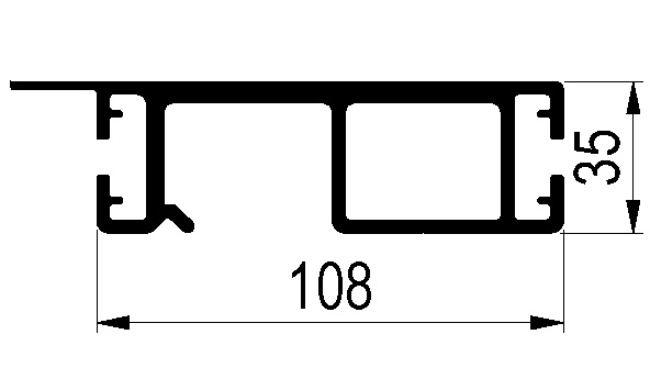
3.3. Auxiliary Profile
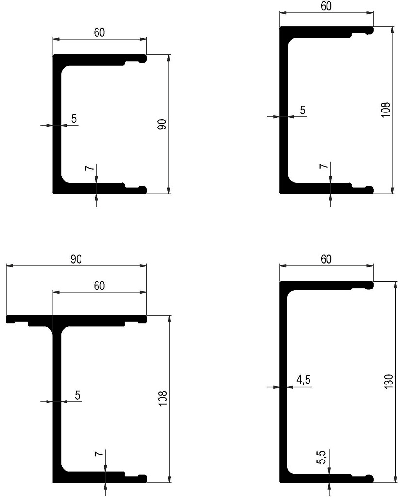
| TT-number | Name | Material/Surface | Weight kg/m |
| 0431001.000 | Auxiliary profile 90 mm | Aluminum natural | 3.13 |
| 0432001.000 | Auxiliary profile 90 mm | Aluminum anodized | 3.13 |
| 0431005.000 | Auxiliary profile 108 mm | Aluminum natural | 3.37 |
| 0432005.000 | Auxiliary profile 108 mm | Aluminum anodized | 3.37 |
| 0431010.000 | Auxiliary profile T 108 mm | Aluminum natural | 3.88 |
| 0431012.000 | Auxiliary profile 130 mm | Aluminum natural | 3.20 |
| 0432012.000 | Auxiliary profile 130 mm | Aluminum anodized | 3.20 |
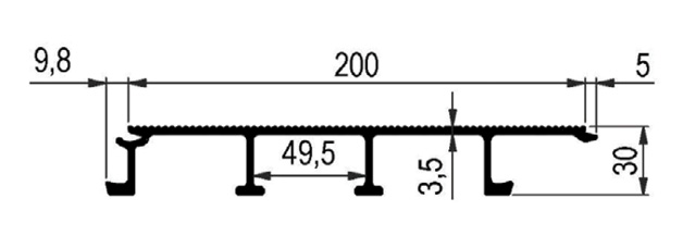
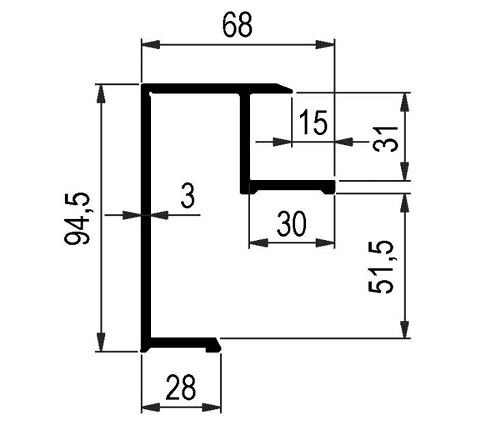
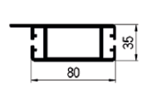
3.4. Profiles for Modular Aluminum Floor
| TT-number | Name | Material/Surface | Weight kg/m |
| 0431206.000 | Perimeter frame profile for 30 mm floor | Aluminum natural | 1.90 |
| TT-number | Name | Material/Surface | Weight kg/m |
| 0431201.000 | Floor profile 200 / 30 mm | Aluminum natural | 3.05 |
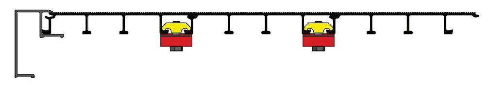
Example of modular floor joint using Palcom clamps:
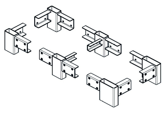
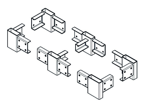
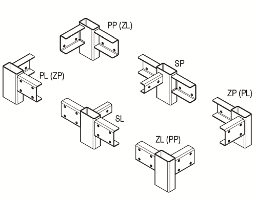
3.5. Mounting Corners
Mounting corners for aluminum platforms are key to the strength and stability of the entire structure. These corner elements are the essential building blocks ensuring that the structure remains firmly connected and resistant to operational demands. Choosing between pre-drilled and non-drilled corners is important depending on the platform and construction requirements.
Key points for mounting installation:
- Distinguishing between pre-drilled and non-drilled mounting corners.
- Using specifically designated bolts and nuts for secure connection.
- Considering the structural requirements of the given aluminum platform.
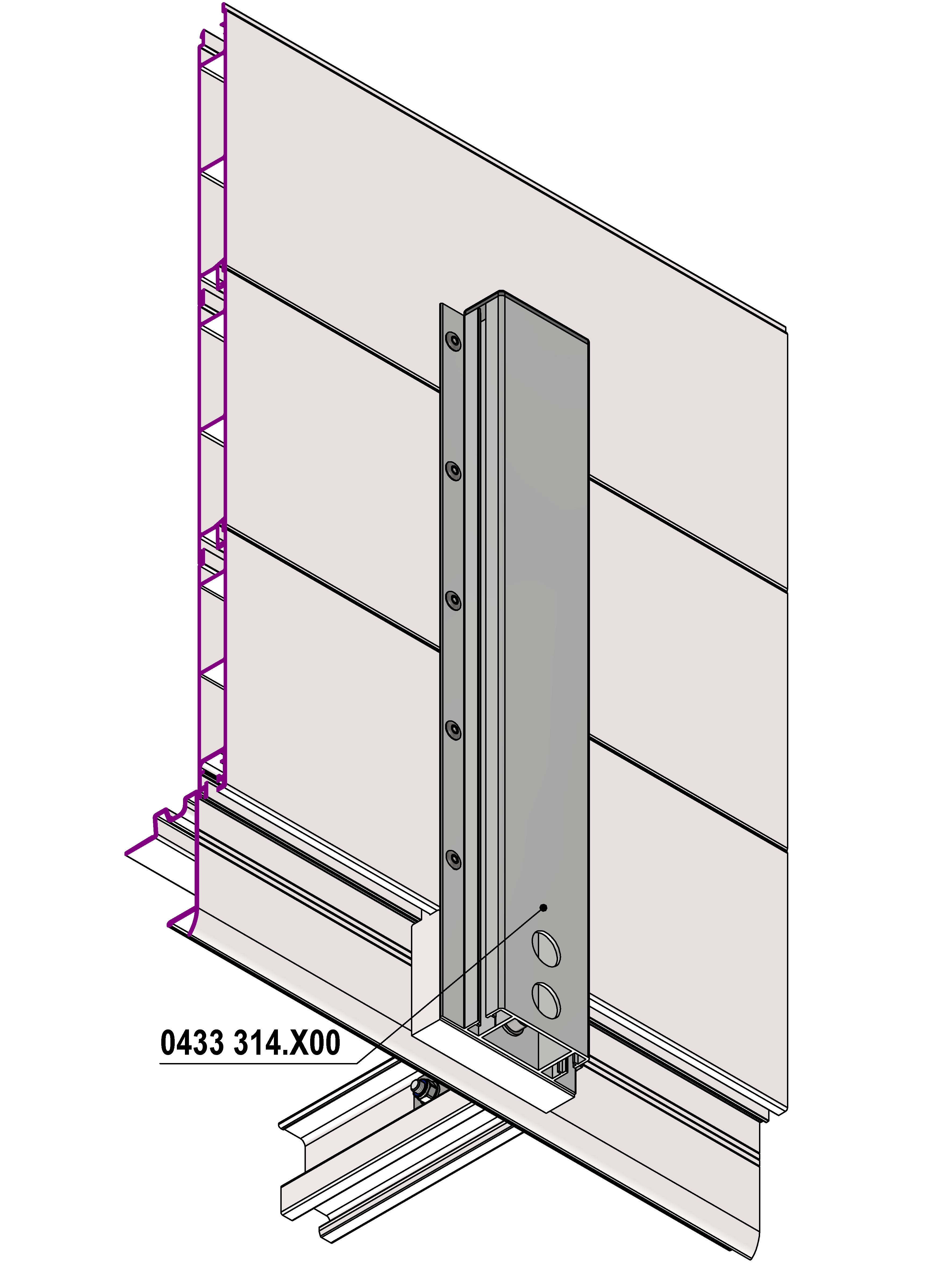
3.5.1. Pre-drilled mounting corners for 80x35 columns
Front and rear corners 80 x 40 mm are pre-drilled for aluminum columns 80 x 35 mm (0354310.100 and 0354320.100).
Related components
 |
Frame profile |
 |
Column 80x35 0354320.x00 |
 |
Column 80x35 0354310.x00 |
3.5.2. Pre-drilled mounting corners for LIGHT columns
Front corners 80 x 40 mm and rear corners 120 x 40 mm are pre-drilled for aluminum LIGHT columns (0354200.xxx and 0354220.xxx).
Related components
|
|
Frame profile |
 |
Aluminum Light column 0354220.x00 |
 |
Aluminum Light column 0354200.x00 |
3.5.3. Non-drilled mounting corners – 70 mm frame
Non-drilled corners for 70 mm frame, for columns 80x33 galvanized 0311 3xx.xxx or custom.
3.5.4. Accessories for platform corner connectors
Designed for 70 and 90 mm frames, for tightening side tarpaulin systems. Holders are inserted into the rear corner parts of the platform.
3.5.5. Non-drilled mounting corners – 90 mm frame
Non-drilled corners for 90 mm frame, columns as selected.
3.5.6. Non-drilled mounting corners for MIDI columns – 90 mm frame
Non-drilled corners for MIDI columns, CS platform, and 90 mm frame.
3.5.7. Non-drilled mounting corners – 108 mm frame
Non-drilled corners for 108 mm frame, columns as selected.
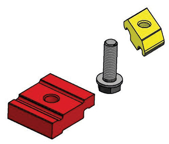
3.6. Parts for Aluminum Platform
| TT-number | Name | Quantity | Surface/Material | Weight kg/pcs |
|---|---|---|---|---|
| 0433030.000 | Palcom clamp L=44 mm – complete | set | 0.22 | |
| 0433031.000 | Part with M10/20 mm thread | 1 | Aluminum | 0.02 |
| 0433032.000 | Part 10.5/44 mm with bolt and washer | 1 | Al / Zn | 0.11 |
| 0433030.100 | Palcom clamp L=100 mm – complete includes: | set | ||
| 0433033.000 | Part with thread + bolt + washer | Al / Zn | 0.09 | |
| 1211851.010 | High-strength adhesive for bolt securing CYBERBOND | 0.01 |
4. Platform Installation
The platform serves as the load-bearing element of the entire superstructure. It consists of aluminum profiles and steel corners, which are later used for mounting aluminum columns.
4.1. Auxiliary Profiles
- Platform installation begins by setting the spacing of the cut auxiliary profiles (longitudinals) to the required dimension with a tolerance of ± 1 mm. Cross profiles are connected to the auxiliary profile with Palcom clamps at given distances. Adhesive for screw joints must be used when installing Palcom clamps.
- Variants of longitudinal profile end modifications for their projection in front of the frame profile:
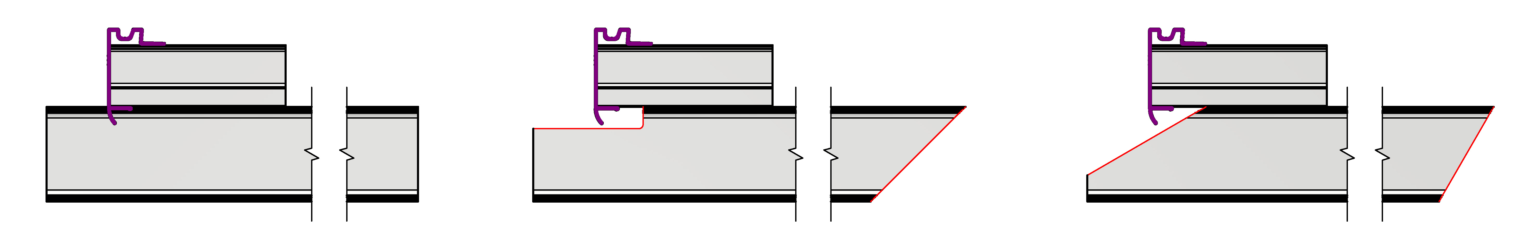
Variant 1
Connecting front reinforcements with longitudinal profiles. Milling the front frame profile (no need to mill longitudinal profiles).
Variant 2
Milling longitudinal profiles into a rounded rectangle shape.
Variant 3
Connecting front reinforcements with longitudinal profiles. Cutting longitudinal profiles at a 30° angle.
4.2. Cross Profiles
Cross profiles serve as reinforcement and as the load-bearing part of the floor of the superstructure.
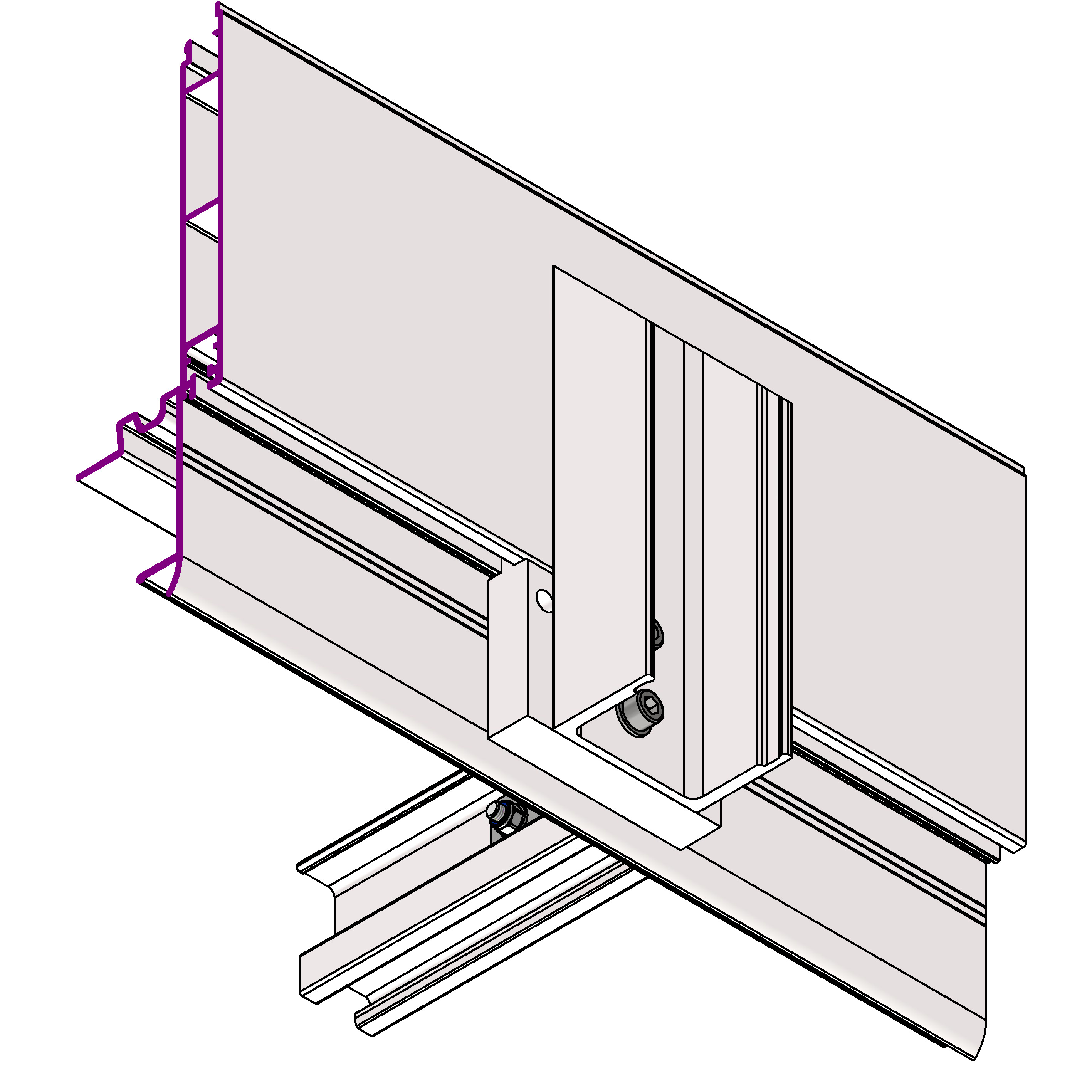
4.3. Frame Profiles and Steel Corners
Frame profiles are fastened with Palcom clamps to cross reinforcements, and at the ends they are screwed to steel corners.
Connection of cross and frame profiles using Palcom clamps
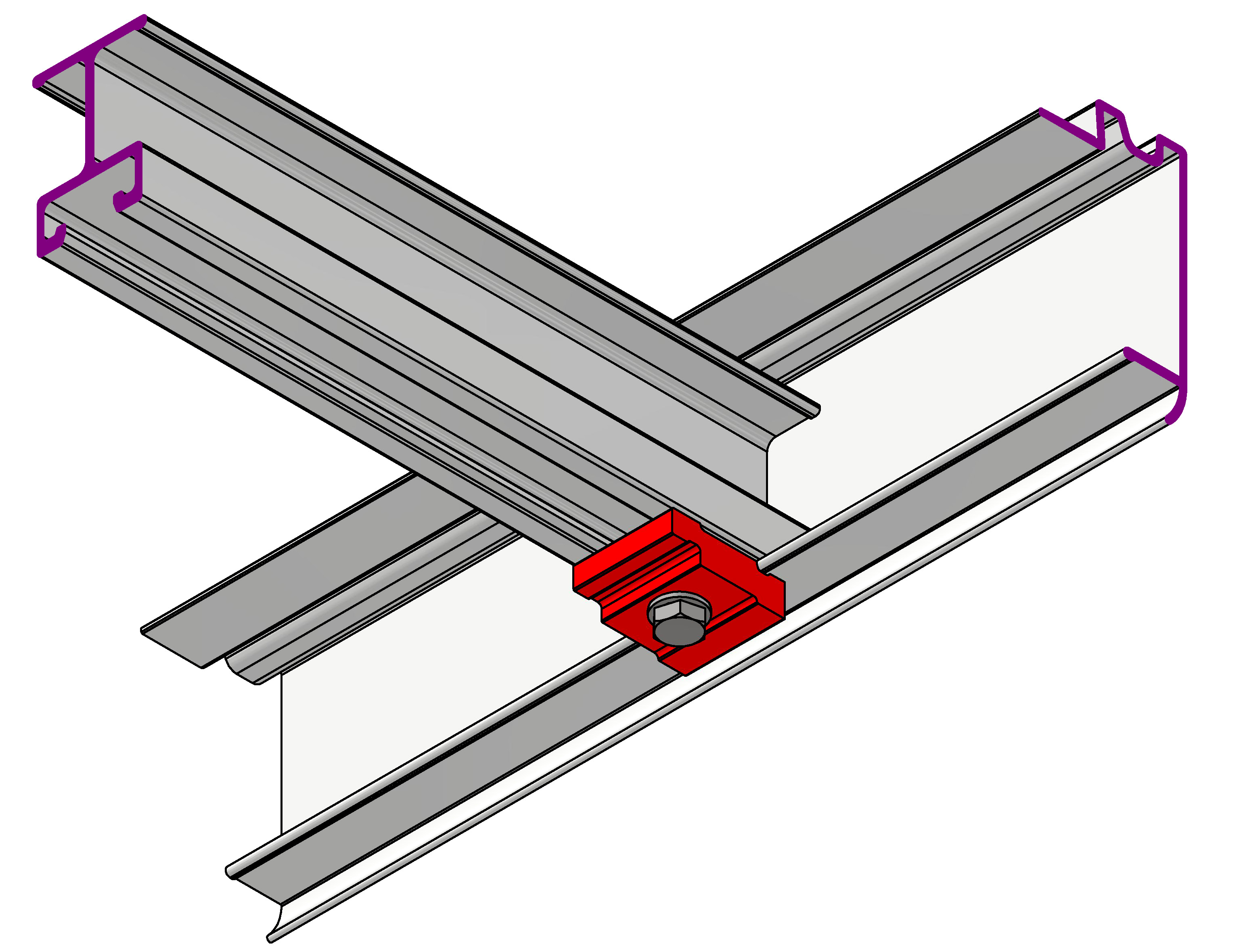
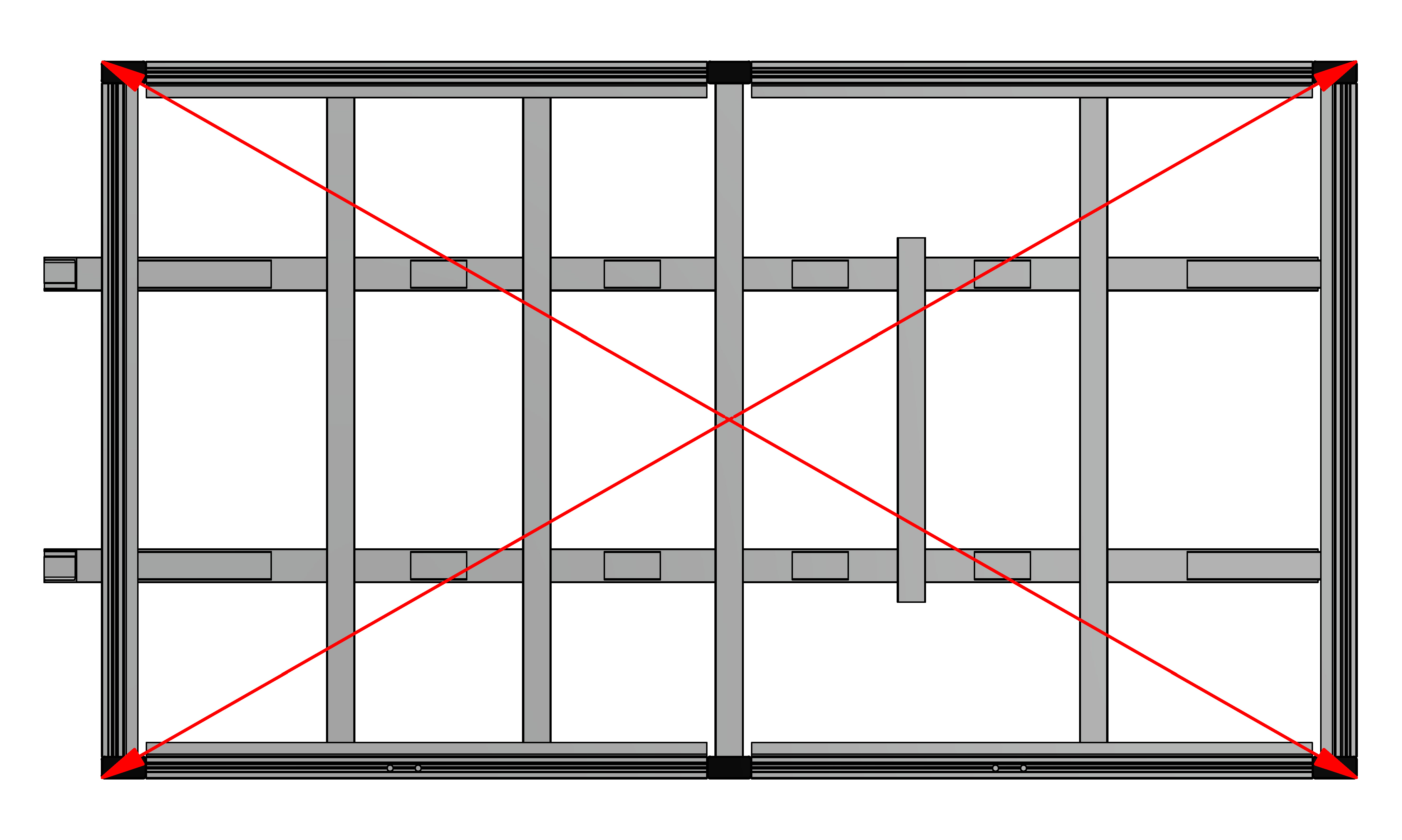
Before tightening the joints, it is necessary to measure and check that the diagonals between corners are equal (|FL;RR| = |FR;RL|).
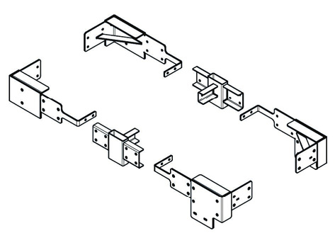
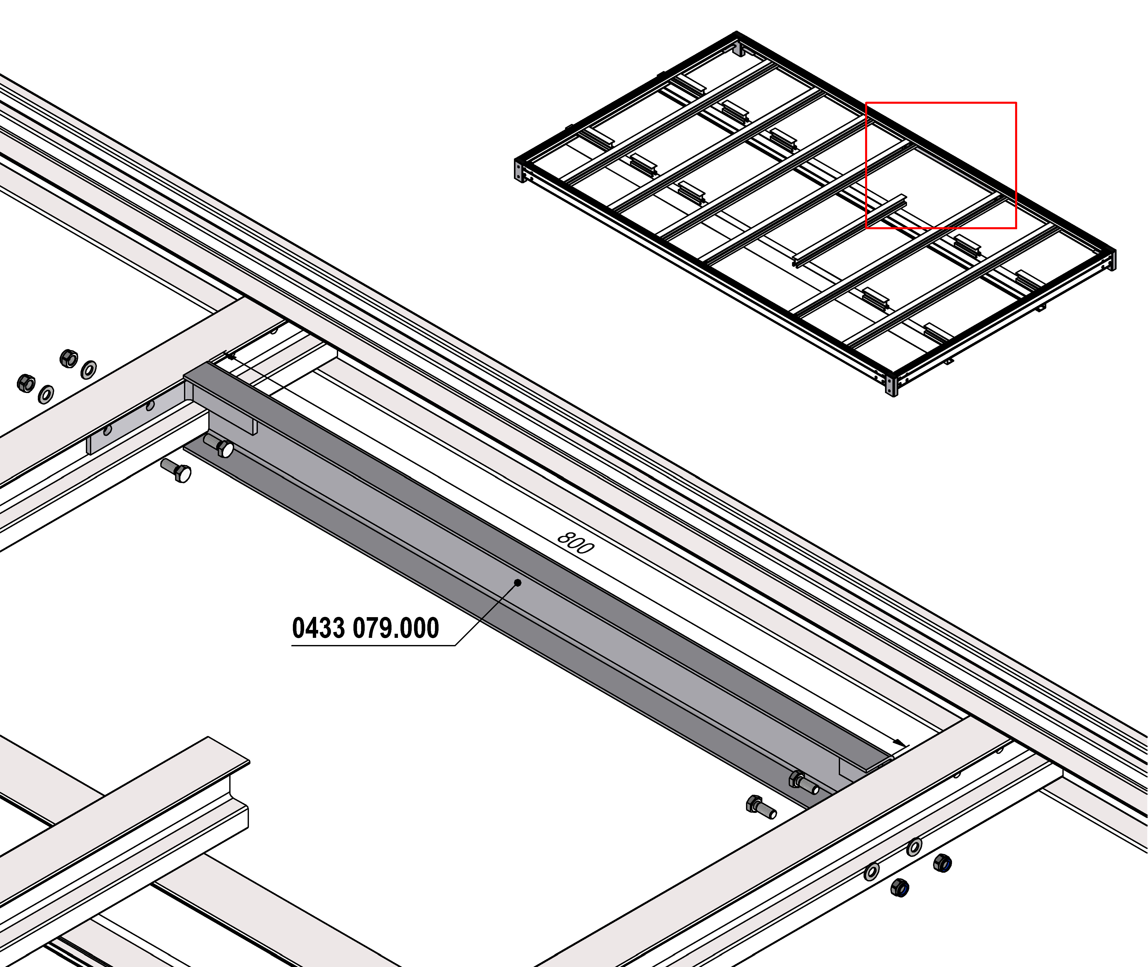
4.4. Central Reinforcements
Steel central reinforcements are used to strengthen the frame profile if central posts are to be mounted in the given position. If the central post is located near or above the axle, a long reinforcement is used; otherwise, a short central reinforcement is applied.
4.5. Front Wall Reinforcements
Reinforcements of the front wall profiles provide strengthening of the front wall. They connect the front wall with frame or cross profiles.
Reinforcement using auxiliary “U” profile
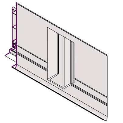
Front wall stop
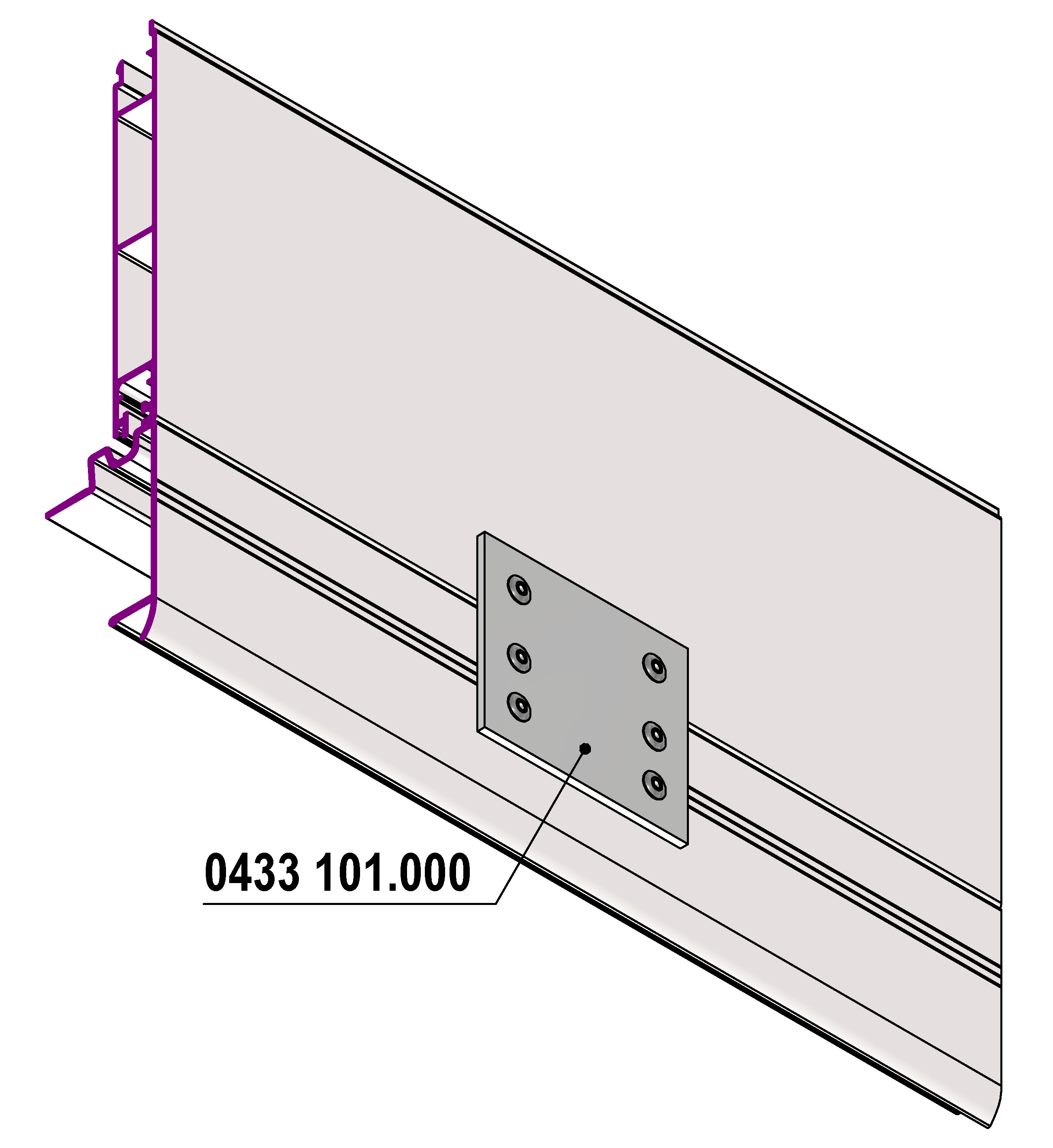
Reinforcement with spacer plate and central post
Reinforcement with auxiliary “U” profile
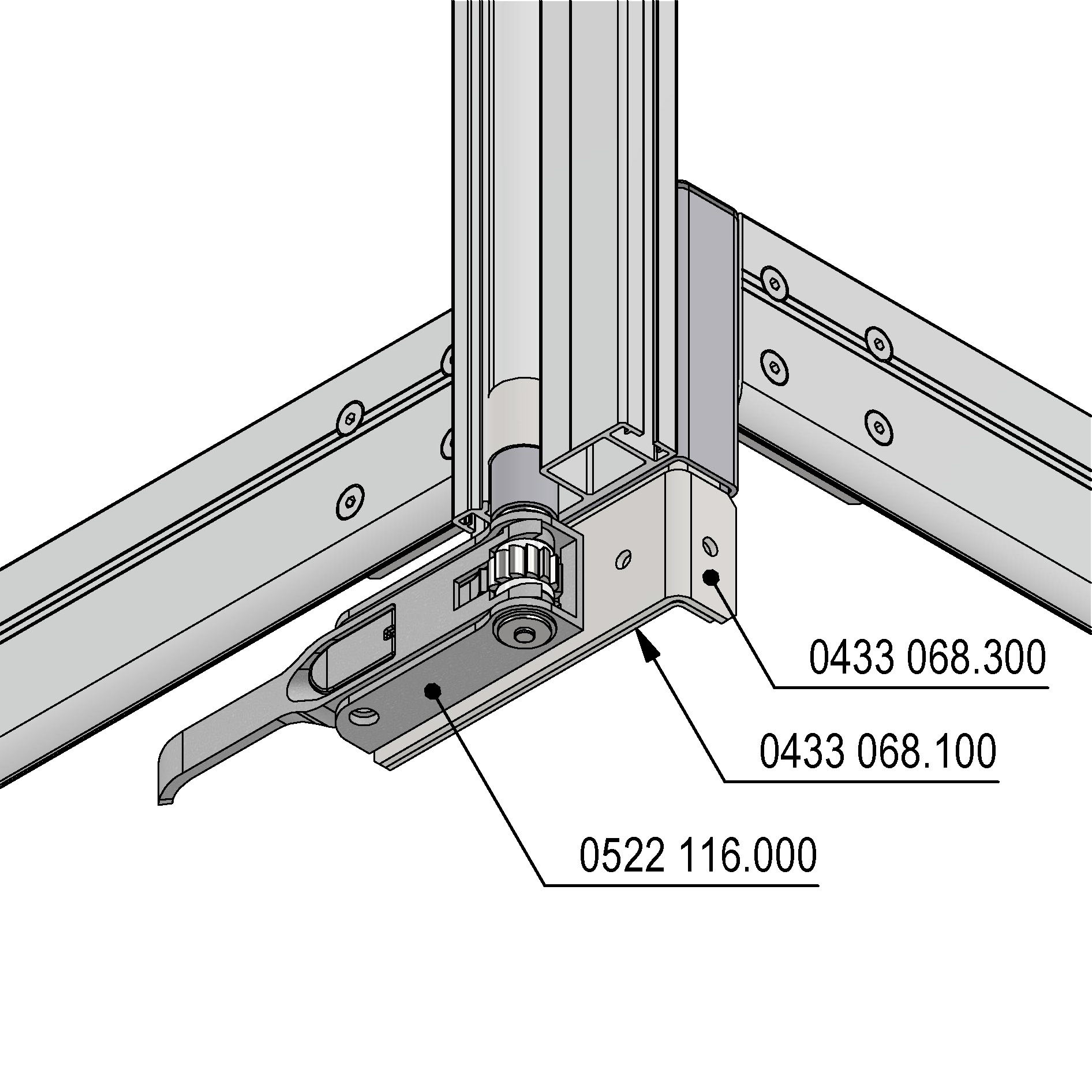
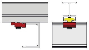
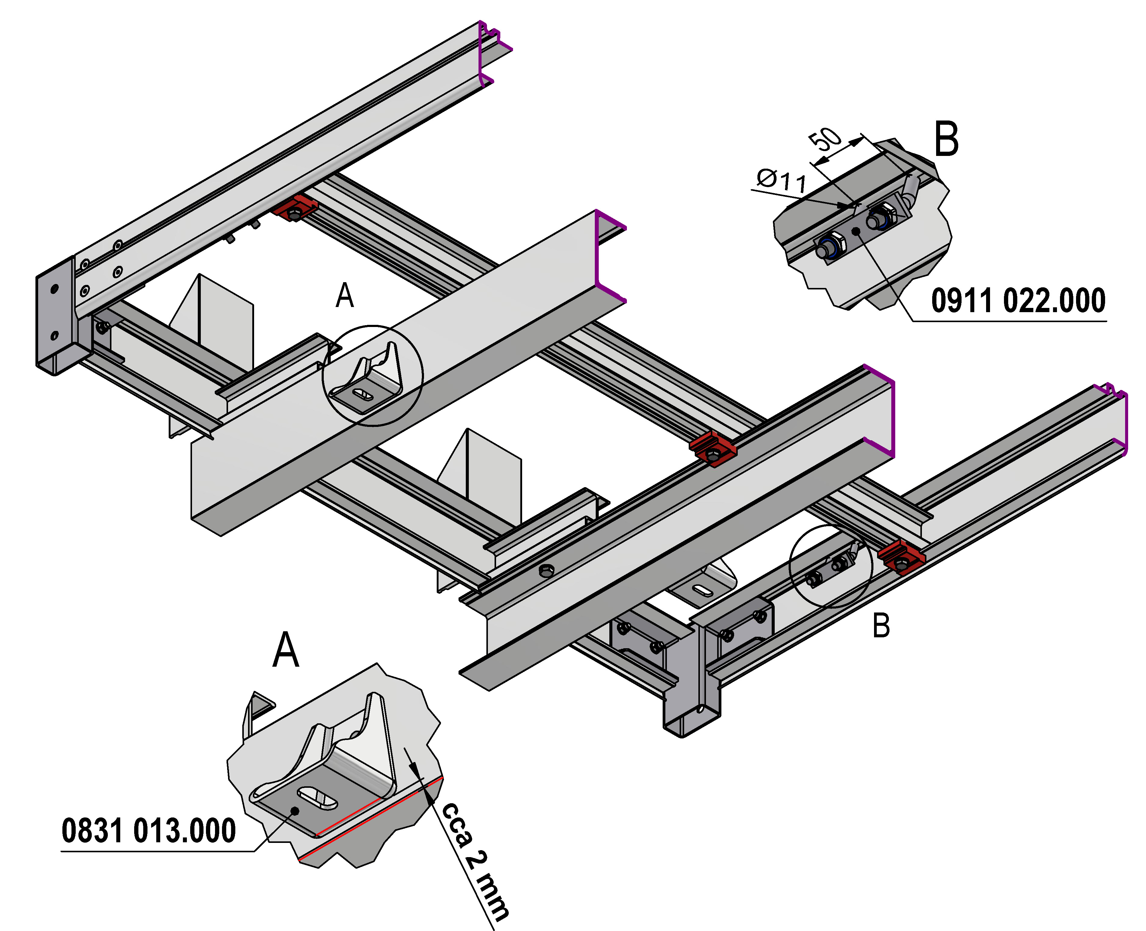
4.6. Anchor Brackets and Clamps on Chassis
- Anchor brackets are mounted into the frame profile and serve to secure the load with lashing straps.
- Clamps are mounted to auxiliary profiles and connect the vehicle body to the vehicle chassis.
5. Warranty and Spare Parts
Our parts are covered by a 12-month warranty under the law from the date of delivery, covering all defects and faults of our parts and construction. The warranty applies to replacement of parts recognized as defective. The warranty is void if the buyer or a third party makes changes or repairs to the delivered goods without prior approval from our company, or in cases of improper use or poor maintenance. For our superstructures, we recommend using tarpaulin with a weight of at least 900 g/m².
Supply and delivery of spare parts and accessories is ensured by:
TRANS–TECHNIK spol. s r.o.
Tyršova 1146
664 42 Modřice